A complete continuous carbonization line is an industrial system designed to convert biomass or organic residues into biochar (or charcoal) through controlled heating in a low-oxygen environment. Unlike batch kilns, a continuous line runs steadily with stable feeding, consistent product quality, and predictable operating costs. Typical feedstocks include wood chips, rice husk, coconut shell, bamboo, sawdust briquettes, or nut shells. Because feedstock characteristics vary widely, the line layout and utilities are usually planned around moisture level, particle size, and the targeted carbonization temperature.
Typical Layout: From Feeding to Finished Biochar
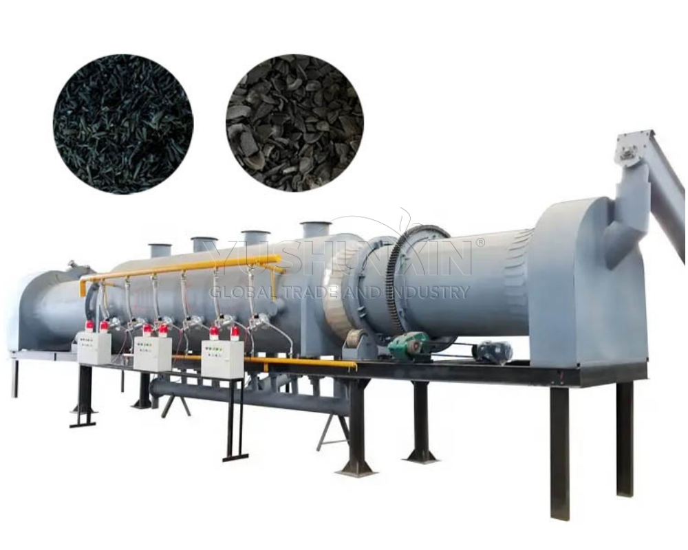
Most lines follow a modular layout that starts with pre-treatment and ends with cooling and packaging. The front end often includes a hopper, conveyor, metering feeder, and (when needed) a dryer to reduce moisture for efficient carbonization. Material then enters the continuous carbonizer reactor—commonly a rotary drum, screw-type reactor, or multi-hearth design—where heat is supplied indirectly by an external furnace or hot gas jacket.
Downstream, hot char must be cooled safely to prevent re-ignition. A sealed char cooler (water-jacket or inert cooling screw) is common, followed by screening to remove fines or classify product size. The line may finish with a silo, bagging station, or briquetting unit depending on the market. Parallel to the solid flow, a gas handling train collects pyrolysis gas, removes dust and tar, and routes cleaned gas back to the burner as fuel—improving energy efficiency and reducing emissions.
Capacity Planning: What Determines Throughput
Capacity is usually rated in tons of raw feedstock per day or tons of char output per hour, and the conversion yield depends on feedstock and temperature. For example, dry woody biomass might yield roughly 25–35% char by mass, while other residues can differ. Throughput is constrained by feeder stability, reactor residence time, heat transfer area, and allowable moisture. A “3 t/h feed” line might produce around 0.8–1.1 t/h of char under typical conditions, but real output should be sized with lab tests and a pilot run to confirm yield, ash content, and fixed carbon targets.
Power Requirement: Major Loads and Typical Ranges
Electrical power demand in a continuous carbonization line is driven mainly by motors and fans, not by heating (because heating is often supplied by burning recovered pyrolysis gas). Key electrical loads include the feeder and conveyors, reactor drive (drum rotation or screw), induced draft fan, dust collection, cooling system drives, and packaging equipment. Small-to-medium industrial lines often fall in the range of tens to a few hundred kilowatts, depending on capacity and the number of auxiliaries (dryer, briquetter, pelletizer, etc.). Fans and air pollution control devices can be especially significant if strict emissions standards require high-pressure drops through filters or scrubbers.
Utilities, Footprint, and Commissioning Considerations
Beyond power, the layout must reserve space for safe maintenance access, fire prevention, and controlled traffic flow for raw material and finished product. Utility planning typically includes cooling water (or a closed-loop system), instrument air, and basic automation for temperature, oxygen, and pressure control. A well-designed continuous carbonization line balances capacity with reliable feeding, stable thermal control, and effective gas cleanup—so the plant runs continuously, meets environmental requirements, and produces consistent char quality day after day. Visiting: https://www.char-molder.com/product/continuous-carbonization-furnace/
Leave a Reply